ESP32-C6 ESP-Hosted over SPI on Jetson Orin Nano - Project Guide
Goal: Bring up an ESP32-C6 as an external Wi-Fi coprocessor on the Jetson Orin Nano 8GB Developer Kit using ESP-Hosted-NG over SPI, so the Jetson gets a normal Linux wireless interface driven through the 40-pin header.
Hub: Network and Connectivity
Related local guides: Peripheral Access · Orin Nano GPIO/SPI/I2C/CAN deep-dive
1. Why this project matters
The Jetson Orin Nano developer kit does not include onboard Wi-Fi. In many edge builds you solve that with a USB dongle or an M.2 Key E card, but an ESP32-C6 + ESP-Hosted-NG path teaches a different and more embedded-friendly pattern:
- the Jetson stays the main Linux application processor
- the ESP32-C6 acts as a dedicated connectivity peripheral
- SPI and GPIOs become part of your system integration work
- the final result still looks like a standard Linux network interface on Jetson
This makes it a strong project for anyone learning how Linux, GPIO interrupts, board wiring, and wireless connectivity fit together on an AI edge device.
Important scope note: this is not just a firmware flash. Espressif documents Raspberry Pi as the reference Linux SPI host. On Jetson, the ESP firmware stays upstream, but the Linux host integration needs a small platform port for SPI bus selection, GPIO mapping, and driver loading.
2. Target architecture
Jetson Orin Nano 8GB dev kit
  |
  |-- SPI1: MOSI / MISO / SCLK / CS0
  |-- GPIO: Handshake / Data Ready / Reset
  |
  +--> ESP32-C6 running ESP-Hosted-NG (SPI peripheral)
         |
         +--> 2.4 GHz Wi-Fi connection to the network

Linux on Jetson then uses wlanX through the normal stack:
NetworkManager / nmcli / wpa_supplicant / hostapd / ip / iw
Target outcome
- Jetson exposes a usable
wlanXinterface through ESP-Hosted nmcli dev wifi listworks on the Jetson- Jetson can join an AP and pass normal traffic
- the transport is stable enough to measure with
pingandiperf3
3. Hardware and software prerequisites
Hardware
- Jetson Orin Nano 8GB Developer Kit
- ESP32-C6 development board with USB access for flashing and power
- 8-10 short jumper wires, ideally under 10 cm
- common ground between Jetson and ESP board
- optional logic analyzer for SPI timing/debug
Software
- JetPack 6.x / L4T 36.x on Jetson
- Linux kernel headers installed on Jetson
gpiod,spi-tools,NetworkManager,iperf3- Espressif esp-hosted repository
- ESP-IDF set up through
esp_hosted_ng/esp/esp_driver/setup.sh
Power and signal safety
- The Jetson 40-pin header uses 3.3 V logic
- Keep the ESP32-C6 on its own USB power during bring-up
- Share ground between boards
- Do not assume the Jetson 3.3 V header pin should power the full ESP dev board during early testing
4. Wiring the Jetson header to ESP32-C6
Espressif's SPI setup guide documents the signal roles for ESP32-C6 on a Raspberry Pi host. On Jetson, keep the same signal roles and remap them onto the Orin Nano's SPI1 header and spare GPIOs.
| Function | Jetson pin | Jetson J12 label | ESP32-C6 pin | Direction |
|---|---|---|---|---|
| MOSI | 19 | SPI0_MOSI |
IO7 |
Jetson -> ESP |
| MISO | 21 | SPI0_MISO |
IO2 |
ESP -> Jetson |
| SCLK | 23 | SPI0_SCK |
IO6 |
Jetson -> ESP |
| CS0 | 24 | SPI0_CS0 |
IO10 |
Jetson -> ESP |
| Handshake | 22 | SPI1_MISO / legacy global GPIO 471 |
IO3 |
ESP -> Jetson |
| Data Ready | 15 | GPIO12 / legacy global GPIO 433 |
IO4 |
ESP -> Jetson |
| Reset | 18 | SPI1_CS0 / legacy global GPIO 473 |
RST or EN |
Jetson -> ESP |
| Ground | 20 or 25 | GND |
GND |
common reference |
Official reference images
Jetson Orin Nano 40-pin header reference:

ESP32-C6-DevKitC-1 pin layout reference:
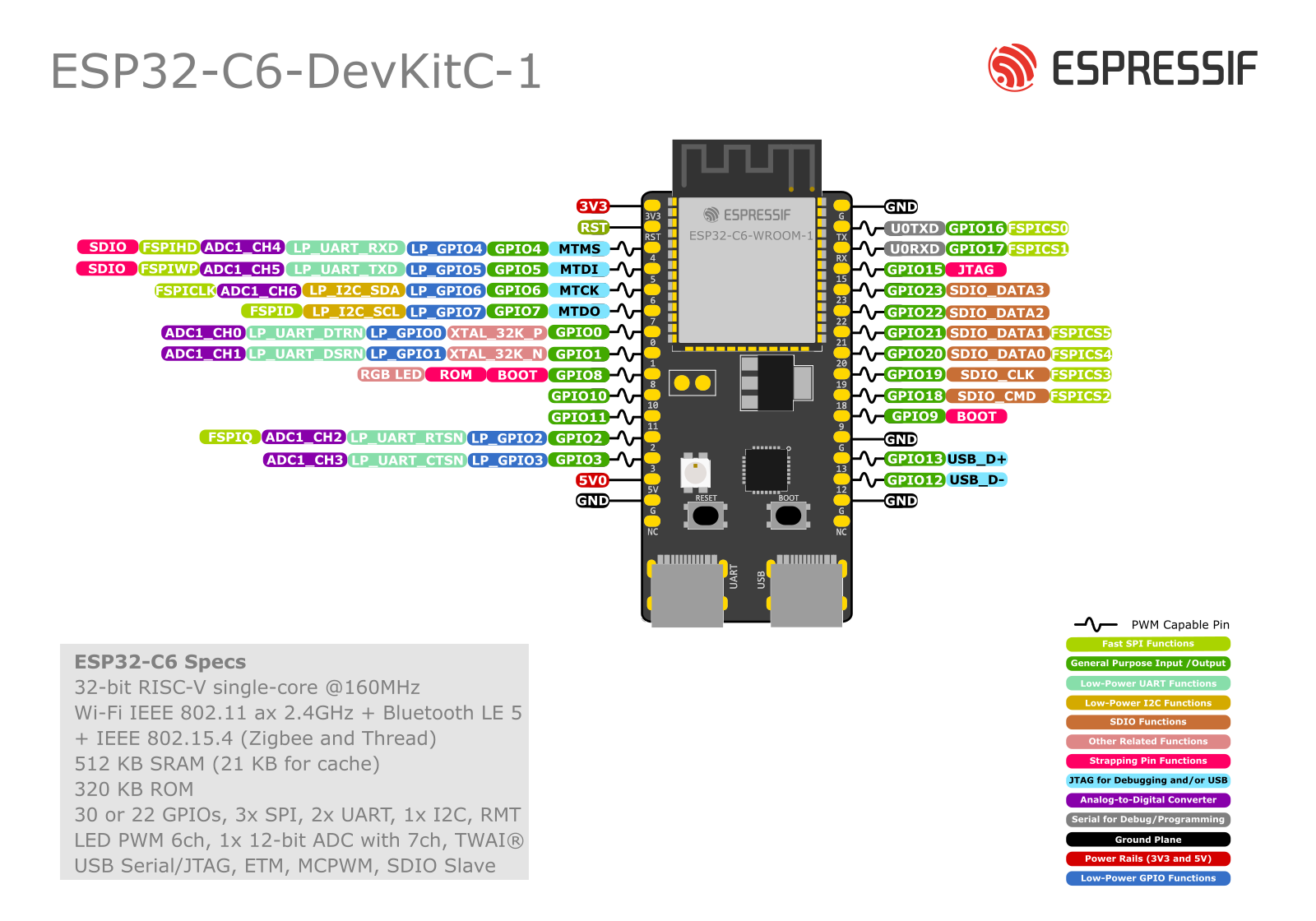
ESP32-C6 DevKitC-1 pinout check
On the official ESP32-C6-DevKitC-1 board, the signals used in this guide are available and can be wired directly by their printed GPIO labels.
For actual bench wiring, use the signal names shown in the guide and on the Espressif board image:
IO7forMOSIIO2forMISOIO6forSCLKIO10forCS0IO3forHandshakeIO4forData ReadyRSTfor reset
That is less error-prone than relying on board header position numbers.
One caution: Espressif documents GPIO4 as a strapping pin on ESP32-C6. Using it for Data Ready can still work, but do not let external wiring force an unsafe level during ESP reset or power-up.
Another practical caution: if the ESP32-C6 RST or EN pin is already wired to Jetson header pin 18, the Jetson side can interfere with USB flashing from your PC. If esptool cannot connect or the ESP keeps resetting during flash, temporarily disconnect only the reset wire from Jetson, or make sure the Jetson host driver is unloaded and not driving that GPIO.
For the three non-SPI control lines in this project, the Jetson host fork uses legacy global Linux GPIO numbers, not gpiochip line offsets. With the J12 pinout used here, the current mapping is:
- pin
15->gpio433for Data Ready - pin
18->gpio473for Reset - pin
22->gpio471for Handshake
Useful J12 pinout excerpt
The Jetson Orin Nano / Nano Super expansion header is J12. In the common Jetson pinout references, I2C and UART pins are assigned by default. Most other non-power pins default to GPIO, and labels such as SPI0_MOSI or SPI1_MISO are suggested functions for those header positions.
For this project, these J12 lines are the useful cross-check:
| J12 pin | J12 label | Linux global GPIO | Use in this project |
|---|---|---|---|
| 13 | SPI1_SCK |
gpio470 |
not used here, but easy to confuse with pin 23 |
| 15 | GPIO12 |
gpio433 |
Data Ready |
| 16 | SPI1_CS1 |
gpio474 |
not used |
| 18 | SPI1_CS0 |
gpio473 |
optional Reset |
| 19 | SPI0_MOSI |
gpio483 |
MOSI |
| 21 | SPI0_MISO |
gpio482 |
MISO |
| 22 | SPI1_MISO |
gpio471 |
Handshake |
| 23 | SPI0_SCK |
gpio481 |
SCLK |
| 24 | SPI0_CS0 |
gpio484 |
CS0 |
| 26 | SPI0_CS1 |
gpio485 |
unused in this project |
| 37 | SPI1_MOSI |
gpio472 |
not used here, but easy to confuse with pin 19 |
This is the naming mismatch you should keep in your head:
- Jetson-IO preset name:
SPI1 - live overlay mux names:
spi1_* - J12 labels on pins
19/21/23/24/26:SPI0_* - Linux device node on the validated dev kit flow:
spidev0.0
On a real Jetson, you can verify those numbers directly with:
Why the extra GPIOs matter
ESP-Hosted SPI is not only a 4-wire SPI bus:
- Handshake tells the host the ESP side is ready
- Data Ready tells the host that the ESP side has data pending
- Reset is required so the host can force the ESP side into a known state
If those three GPIOs are wrong, the SPI transport may partially initialize or fail after the first event.
Recommended bring-up practice
- keep wires short and similar in length
- start on a bench, not inside an enclosure
- label the three non-SPI GPIOs clearly before first power-up
- if you have a logic analyzer, probe
CS,SCLK,Handshake, andData Ready
5. Prepare the Jetson SPI host side
5.1 Enable SPI1 on the 40-pin header
Use Jetson-IO to enable the SPI controller behind header pins 19/21/23/24:
On a fresh Orin Nano dev kit, Jetson-IO often shows the header in a mostly unassigned state, for example:
|                    unused ( 19) .. ( 20) GND                       |
|                    unused ( 21) .. ( 22) unused                    |
|                    unused ( 23) .. ( 24) unused                    |
|                       GND ( 25) .. ( 26) unused                    |
That is the starting state, not an error. It means the SPI function is not yet mapped onto those header pins.
Use this menu flow:
Configure Jetson 40-pin HeaderSPI1 (1 device)Save and reboot to reconfigure pins
Why SPI1 (1 device):
- this project uses only CS0 on pin
24 - pin
26is not needed by the ESP32-C6 in this project - pins
15,18, and22should remain available as ordinary GPIO lines forData Ready,Reset, andHandshake
After the reboot, pins 19, 21, 23, and 24 should no longer be generic unused header pins. They should be assigned to the SPI1 function, and Linux should expose the bus as a spidev device.
When you save successfully, Jetson-IO shows a message like:
Modified /boot/extlinux/extlinux.conf to add following DTBO entries:

/boot/jetson-io-hdr40-user-custom.dtbo

Press any key to reboot the system now or Ctrl-C to abort
That means:
- Jetson-IO generated a device-tree overlay for the 40-pin header
- it added that overlay to
extlinux.conf - the new header mapping will take effect on the next boot
For this project, the correct action is to reboot now so the SPI header mapping becomes active.
After reboot:
On the developer kit, the header's SPI1 controller typically appears to Linux as /dev/spidev0.0.
If you see something like:
that means:
- the SPI device node exists
- the Jetson side has exposed the bus to Linux
- users in the
gpiogroup can open it
On some systems you may also see:
Interpret that carefully:
spidev0.0is still the most likely candidate for the 40-pin header SPI1 CS0 devicespidev0.1means a second chip-select is also exposed on the same busspidev1.0andspidev1.1mean another SPI controller is available somewhere in the system
For this project, do not assume every spidev node belongs to the 40-pin header. Use the Jetson-IO overlay and the physical header pin mapping to identify the correct bus.
It does not mean the full ESP-Hosted project is working yet. It only proves the Jetson SPI bus is available. You still need:
- correct wiring to the ESP32-C6
- correct
Handshake,Data Ready, andResetGPIO mapping - ESP32-C6 firmware built for SPI
- the Linux ESP-Hosted host side ported and loaded correctly
5.1.1 What "unused" means in this project
Jetson-IO uses unused to mean "not currently assigned to one of the named peripheral presets on the header."
For this project, that is actually what you want for the extra control lines:
- pin
22for Handshake - pin
15for Data Ready - pin
18for Reset
Those three pins do not need to be part of the SPI1 preset. They just need to stay available for GPIO use from Linux.
So the clean target state is:
- pins
19/21/23/24assigned to SPI1 - pins
15/18/22left available as GPIO
If Jetson-IO or another overlay assigns one of those control pins to some other peripheral, fix that before continuing.
5.1.2 Read the Jetson-IO overlay like an engineer
If you decompile the generated overlay:
sudo dtc -I dtb -O dts \
  -o /tmp/jetson-io-hdr40-user-custom.dts \
  /boot/jetson-io-hdr40-user-custom.dtbo
you will see entries like:
hdr40-pin19 {
    nvidia,pins = "spi1_mosi_pz5";
    nvidia,function = "spi1";
};

hdr40-pin21 {
    nvidia,pins = "spi1_miso_pz4";
    nvidia,function = "spi1";
};

hdr40-pin23 {
    nvidia,pins = "spi1_sck_pz3";
    nvidia,function = "spi1";
};

hdr40-pin24 {
    nvidia,pins = "spi1_cs0_pz6";
    nvidia,function = "spi1";
};

hdr40-pin26 {
    nvidia,pins = "spi1_cs1_pz7";
    nvidia,function = "spi1";
};
This is the part that matters most for teaching:
hdr40-pin19means physical header pin 19nvidia,pins = "spi1_mosi_pz5"means the SoC pad behind that header pin is the pad NVIDIA namesspi1_mosi_pz5nvidia,function = "spi1"means Jetson-IO is assigning that pad to the SPI1 peripheral function
So in plain language, that block says:
- pin
19is now SPI1 MOSI - pin
21is now SPI1 MISO - pin
23is now SPI1 SCLK - pin
24is now SPI1 CS0 - pin
26is now SPI1 CS1
That is exactly what this ESP32-C6 project needs.
Real bring-up note: on some Jetson-IO results, SPI1 (1 device) still produces an overlay that muxes pin 26 to spi1_cs1_pz7 and also exposes /dev/spidev0.1. That is acceptable for this project. You simply leave pin 26 and spidev0.1 unused unless you intentionally add a second SPI target.
5.1.3 What the other device-tree sections mean
Your decompiled overlay also contains sections like:
fragment@0fragment@1__symbols____fixups__
Short explanation:
fragment@0is the main pinmux change for the normal Tegra pin controllerfragment@1is the companion block for the AON pin controller; for this SPI1 change it usually does not carry the interesting header remap lines__symbols__gives names to nodes inside the overlay so other parts of the device tree can refer to them__fixups__tells the bootloader or device-tree loader where to apply the overlay against the base board device tree
You do not need to understand every overlay internals detail to use Jetson-IO well. For practical bring-up, the key test is:
- the overlay exists in
/boot/jetson-io-hdr40-user-custom.dtbo extlinux.confreferences it- the overlay maps header pins
19/21/23/24tospi1 /dev/spidev0.0exists after reboot
If all four are true, the Jetson side SPI pinmux is in the right state.
5.1.4 What pin 26 means in practice
There are two valid outcomes you may see after selecting SPI1 (1 device):
- Only the
CS0path is obvious in the overlay and/dev/spidev0.0 - Both
CS0andCS1are muxed, and Linux also exposes/dev/spidev0.1
If pin 26 appears as:
that means Jetson-IO also mapped header pin 26 to SPI1 CS1.
That does not break this project. It only means:
- the header bus now has a second available chip-select
- Linux may expose
/dev/spidev0.1 - you should leave pin
26physically unconnected for this ESP32-C6 setup
This project still uses:
spidev0.0CS0on pin24- one ESP32-C6 target only
5.1.5 Live device-tree verification on a real Jetson
After reboot, you can also dump the live device tree:
It is normal for that command to print a large number of warnings on Jetson. Those warnings usually reflect how NVIDIA ships the live tree and do not mean your SPI setup failed.
For this project, the useful checks are much narrower:
/boot/extlinux/extlinux.confcontains:OVERLAYS /boot/jetson-io-hdr40-user-custom.dtbo/boot/jetson-io-hdr40-user-custom.dtboexists- the decompiled overlay maps header pins
19/21/23/24tospi1 /dev/spidev0.0exists after reboot
If those are true, the Jetson side SPI header setup is correct enough to continue.
You can go one level deeper and prove which Linux SPI controller each spidev node belongs to:
Example from a real Orin Nano dev kit:
== spidev0.0 ==
/sys/devices/platform/bus@0/3210000.spi/spi_master/spi0/spi0.0
== spidev0.1 ==
/sys/devices/platform/bus@0/3210000.spi/spi_master/spi0/spi0.1
== spidev1.0 ==
/sys/devices/platform/bus@0/3230000.spi/spi_master/spi1/spi1.0
== spidev1.1 ==
/sys/devices/platform/bus@0/3230000.spi/spi_master/spi1/spi1.1
That is the clean proof that:
- the 40-pin header path selected in Jetson-IO as
SPI1maps to Linuxspi0and thereforespidev0.* spidev0.0is the CS0 device you want for this projectspidev0.1is the same controller's CS1spidev1.0andspidev1.1are a different SPI controller
This naming mismatch is normal on Jetson. The board-facing name is header SPI1, while the Linux-visible bus name is often spi0.
5.2 Install useful tools
sudo apt update
sudo apt install -y \
  linux-headers-$(uname -r) \
  libgpiod-dev gpiod \
  spi-tools \
  network-manager \
  iperf3
5.3 Verify the basic SPI path first
Before loading the ESP-Hosted driver, make sure the controller is alive and the header is configured correctly.
- confirm
/dev/spidev0.0exists - list all SPI device nodes with
ls /dev/spidev* - confirm Jetson-IO no longer shows pins
19/21/23/24as plainunused - confirm your chosen GPIO lines are free for use
- verify there is no conflicting device already bound to the same bus/chip-select
If /dev/spidev0.0 already exists before you start this guide, your Jetson may already have SPI1 enabled from an earlier Jetson-IO configuration. In that case, you are already past the "enable SPI bus" step on the Jetson side, but you still need to finish the ESP-Hosted wiring and host-driver work.
If you also see spidev0.1, that usually means CS1 is available on the same header SPI bus. Ignore it for this project.
If you see additional nodes like spidev1.0 and spidev1.1, treat them as different SPI controllers until proven otherwise. Do not point the ESP-Hosted host code at them just because they exist.
If you plan to use the Espressif kernel module directly, be aware that generic spidev may need to be disabled once you move from raw SPI sanity checks to the real host driver path.
5.4 Start conservatively
During first bring-up:
- use short wires
- start with 1 MHz SPI clock if timing is unstable
- avoid changing multiple variables at once
6. Build and flash ESP-Hosted-NG for ESP32-C6
Clone the repo and prepare the ESP side exactly from the upstream ESP-Hosted-NG tree:
git clone https://github.com/espressif/esp-hosted.git
cd esp-hosted/esp_hosted_ng/esp/esp_driver
./setup.sh
cd esp-idf
. ./export.sh
cd ../network_adapter
Set the target to ESP32-C6:
Open configuration:
Select the SPI transport:
Example ConfigurationTransport layerSPI interface
Then open Example Configuration -> SPI Configuration and keep the default ESP32-C6 values unless you have a specific reason to change them:
GPIO pin for handshake=3GPIO pin for data ready interrupt=4ESP to Host SPI queue size=20Host to ESP SPI queue size=20SPI checksum ENABLE/DISABLE= enabledDe-assert HS on CS= disabled
Those defaults match Espressif's SPI setup for ESP32-C6:
IO10=CS0IO6=SCLKIO2=MISOIO7=MOSIIO3=HandshakeIO4=Data ReadyRST= reset
When flashing from a Linux host PC, the built-in USB Serial/JTAG port on an ESP32-C6-DevKitC-1 usually appears as /dev/ttyACM0. A device such as /dev/ttyUSB0 is often a separate USB-UART bridge and is not the first port to try for direct C6 flashing.
To identify the right port cleanly:
Then unplug and reconnect the ESP board. The newly appearing ttyACM* device is usually the correct port.
Then build and flash:
Replace /dev/ttyACM0 only if your board appears on a different ttyACM* device.
If you need to prove the port before a full flash, query the chip directly:
Flashing with Jetson wiring attached
If the ESP board is already wired to the Jetson 40-pin header, the safest flashing sequence is:
- Keep the ESP board connected to the host PC over USB.
- Disconnect the Jetson
Resetwire from ESPRSTorEN, or unload the Jetson host driver first. - Flash the ESP firmware from the PC.
- For the proven Jetson bring-up flow in this guide, leave the reset wire disconnected and use
resetpin=-1on the Jetson side. - Only then load the Jetson ESP-Hosted host driver.
If you are using the Jetson port described later in this guide, unloading the host driver looks like this:
This avoids the Jetson reset GPIO interfering with the USB flashing process.
What you should see
- successful build and flash
- ESP boot logs on the serial monitor
- the USB-connected DevKitC-1 appearing as a
ttyACM*device on the host PC - the firmware configured for the same transport you intend to use on the Jetson host side
Do not mix transports. A host built for SPI and an ESP firmware built for SDIO or UART will fail in ways that look like board or timing bugs.
7. Port the Linux host side from Raspberry Pi to Jetson
Espressif ships Raspberry Pi as the reference Linux host. On Jetson, use that host implementation as the starting point rather than trying to invent a new stack.
7.1 Start from the upstream host tree
Relevant upstream locations:
esp_hosted_ng/host/esp_hosted_ng/host/spi/esp_hosted_ng/docs/setup.mdesp_hosted_ng/docs/porting_guide.md
The Raspberry Pi helper script is useful as upstream reference only:
On Raspberry Pi the documented entry point is:
On Jetson, do not use rpi_init.sh as your main bring-up path. It is Raspberry Pi specific. For the Jetson Orin Nano flow described in this guide, use the Jetson-oriented fork and its host README instead:
esp_hosted_ng/host/README.mdesp_hosted_ng/host/jetson_orin_nano_init.sh
That path already captures the validated Jetson settings in this guide:
resetpin=-1spi_handshake_gpio=471spi_dataready_gpio=433spi_bus_num=0spi_chip_select=0spi_mode=2clockspeed=10
7.2 Jetson-specific porting work
Port these pieces to Jetson:
-
Reset GPIO Jetson header pin
18maps to legacy global GPIO473, but on the validated bring-up in this guide the host keeps that path disabled withresetpin=-1. That avoids the Jetson holding the ESP in reset or interfering with USB flashing. Only opt in toresetpin=473after you have separately proven that your reset wiring is stable. -
Handshake and Data Ready GPIOs Update the host SPI definitions so they match your chosen Jetson GPIO header pins:
- handshake on pin
22-> legacy global GPIO471 -
data ready on pin
15-> legacy global GPIO433 -
SPI bus and chip select selection Set the host-side SPI bus and chip-select values to match the Linux-visible device behind the header. On the validated Orin Nano dev kit flow in this guide, that is:
- header
SPI1 - Linux controller
spi0 - device node
spidev0.0 - sysfs path
3210000.spi - host module values:
bus 0,chip-select 0
If your system also exposes spidev0.1, leave that unused unless you intentionally move to a second target on CS1. Do not switch to spidev1.* unless you have separately proven that a different controller is the one you want.
- Device tree and pinmux Make sure:
- SPI1 is enabled on the 40-pin header
- the three extra GPIOs are free and configured for GPIO use
-
no conflicting overlay or driver claims the same pins
-
spidevconflict handling Once you move to the real ESP-Hosted kernel module path, disable genericspidevif it prevents the Espressif driver from claiming the bus. -
Build environment If you build on-device, point the host build at Jetson kernel headers. If you cross-compile, update
ARCH,CROSS_COMPILE, and kernel paths foraarch64.
7.2.1 Practical Jetson host path
A Jetson-oriented fork now exists at:
https://github.com/ai-hpc/jetson-esp-hosted
It adds:
- a Jetson-specific helper script:
esp_hosted_ng/host/jetson_orin_nano_init.sh- a Jetson host README:
esp_hosted_ng/host/README.md- module parameters for:
- SPI bus number
- chip select
- handshake GPIO
- data-ready GPIO
- SPI mode
On a real Jetson Orin Nano dev kit, that helper has already been validated to:
- build
esp32_spi.ko - unbind
spi0.0from genericspidevfor the current boot - insert the ESP-Hosted SPI host module cleanly
- keep the runtime SPI clock capped at
10 MHzeven when the ESP boot-up event requests26 MHz - bring up
wlan0after a manual ESP reset withresetpin=-1
That proves the Jetson host driver build/load path and the working SPI/Wi-Fi transport path are both real on this hardware. The validated sequence is:
- load the Jetson module with
resetpin=-1 - keep
sudo dmesg -wopen - manually press the ESP reset button
- wait for the ESP boot-up event, chipset detection, clock clamp, and
wlan0
7.3 Good bring-up order
Use this order. It reduces ambiguity.
- Enable SPI1 and verify
/dev/spidev0.0 - Verify that any additional
spidev1.*nodes are not the bus you intend to use - Confirm Jetson GPIO choices physically match your wiring
- Flash the ESP32-C6 with SPI-enabled ESP-Hosted firmware
- Port the host-side GPIO mapping and bus selection
- Start with
resetpin=-1andclockspeed=10 - Load the host module, then manually press the ESP reset button
- Watch
dmesgfor the ESP boot-up event, chipset detection, and the 26 MHz request being clamped to 10 MHz - Confirm
wlan0appears - Only then move to Wi-Fi association and throughput tests
8. Validation checklist
8.1 Transport-level validation
You want to see:
- the Jetson-side driver loads cleanly
- the host receives the first event from the ESP side after you manually reset the ESP
- chipset detection succeeds
- the ESP request for
26 MHzis clamped to the configured host limit of10 MHz
8.2 Interface-level validation
Expected result:
- a new wireless interface such as
wlan0orwlan1 - a Bluetooth controller such as
hci0 hciconfig -ashowsBus: SPIbluetoothctl listshows the ESP controller
On the validated Jetson Orin Nano plus ESP32-C6 flow in this guide, the real expected interfaces are wlan0 and hci0.
8.3 Join a network
nmcli dev wifi list ifname wlan0
sudo nmcli dev wifi connect "SSID" password "password"
ip addr show
ping -c 4 8.8.8.8
8.4 BLE discovery smoke test
The ESP32-C6 host path here is BLE-only, not classic Bluetooth audio.
Inside bluetoothctl:
Expected result:
scan onsucceeds- nearby BLE devices appear in
devices showlists the controller roles and advertising features
On the validated flow for this guide, bluetoothctl successfully discovered nearby BLE devices from the ESP32-C6 controller exposed over SPI.
If rfkill shows Wi-Fi as soft-blocked but Bluetooth as unblocked, BLE scan can still work.
You may also see one of these during early BLE bring-up:
Can't read local name on hci0: Input/output error (5)Failed to set local name: Failed (0x03)
Those lines are not ideal, but they did not block BLE scan and discovery on the validated Jetson flow here.
8.5 Basic throughput smoke test
On another machine:
On the Jetson:
Do not optimize too early. First prove:
- stable scan
- stable association
- clean packet flow
- no repeated transport resets
9. Common failure modes
No first event in dmesg
Usually one of these:
- you loaded the host with
resetpin=-1but did not manually reset the ESP yet - reset GPIO is wrong
- handshake or data-ready GPIO is mapped incorrectly
- SPI mode or clock is too aggressive
- ESP firmware is not actually built for SPI
If this happens right after a fresh flash attempt, also make sure the ESP was not being held in reset by the Jetson reset wire during flashing.
First event appears, then traffic stalls
Common causes:
- handshake/data-ready interrupts are not configured correctly on the host
- GPIO edge polarity is wrong
- jumper wires are too long or noisy
- the host driver and ESP firmware are from inconsistent revisions
- the host jumped to a higher SPI clock than the wiring can support
On the validated Jetson fork flow in this guide, keep clockspeed=10. The host clamps the ESP's requested 26 MHz runtime reconfigure back down to 10 MHz.
Bus exists, but the ESP-Hosted driver cannot claim it
Likely cause:
- generic
spidevstill owns the device tree path that the kernel module needs
Wi-Fi interface appears but is unstable
Work through this order:
- Lower SPI frequency to 1 MHz
- Shorten the wires
- Re-check shared ground
- Confirm the ESP board power is clean
- Re-test with a simple AP close to the bench
Transport works, but performance is weak
That is normal early on. Once the path is stable:
- increase SPI clock stepwise
- measure each change
- keep notes on which frequency starts to fail
10. Stretch goals
- add AP mode support and use the ESP32-C6 as the Jetson's provisioning radio
- document GATT workflows and Wi-Fi/BLE coexistence testing from the same ESP-Hosted stack revision
- replace jumper wires with a small adapter board or custom carrier interconnect
- add a device-tree overlay and scripts so the Jetson setup becomes reproducible
- measure power, latency, and throughput against a USB Wi-Fi dongle baseline
11. References
Official upstream references
- Espressif esp-hosted repository
- ESP-Hosted-NG setup guide
- ESP-Hosted-NG SPI protocol notes
- ESP-Hosted-NG Linux porting guide
- ESP32-C6-DevKitC-1 user guide
- ESP32-C6 establish serial connection
- ESP32-C6 USB Serial/JTAG console
- AI-HPC Jetson-oriented jetson-esp-hosted fork